


| Place of Origin: | Guangdong,China |
|---|---|
| Certification: | ROHS,UL,REACH |
| Model Number: | M-TP300 |
| Minimum Order Quantity: | Negotiation |
| Price: | Negotiation |
| Packaging Details: | Packed in Carton |
| Delivery Time: | 3~7Days |
| Payment Terms: | T/T |
| Supply Ability: | 10000Pieces/Day |
| Feature: | Electrical Performence | Sample: | Freely Supplied |
|---|---|---|---|
| Color: | White,Grey | Rated Voltage: | 6Kv/ac |
| Material: | Thermal Interface Pad | Application: | LED |
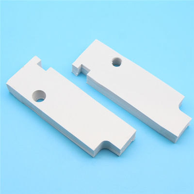
| Size: | 200*400mm. Customized Accepted | Product Name: | Factory Produce Thermal Pad Price |
| Highlight: | 3W/M.K carbon thermal pad,5.5Kgf/cm2 carbon thermal pad,5.5Kgf/cm2 Thermal Conductive Silicone Pad |
||
3W/M.K Grey Silicone Conductive Carbon Thermal Pad For LED Lighting
Heat Transfer Thermal Pad Description
1.Thermal pads are designed as a heat transfer gap filler to fulfil the heat transfer between heat generating and cooling devices.
2.Thermal pads are also insulating and anti-damping and can seal the gaps
3.Different thickness range and thermal conductivity for different requirements.
Heat Transfer Thermal Pad Features
1.Thermal conductivity: 3.0w/m-k
2.Size available: 200mm x 400mm, 300mm x 300mm, special size could be provided
3.Insulation
4.Electrical isolating
5.Flame retarding: V-0
6.Flexible
7.Color: colorful
8.Thermal conductivity: 0.5W/M-K, 1.0W/M-K, 1.5W/M-K, 2.0W/M-K, 2.5W/M-K, 3.0W/M-K,4.0W/M-K
9.Hardness: 30 Shore C, 40 Shore C (Regular), 60 Shore C
Heat Transfer Thermal Pad Features
|
Polyester Release Film
|
|
Silicone Pad (Inherently Tacky) |
|
Polyester Release Film |
Heat Transfer Thermal Pad Application
1.Power supply,powder inverter product,heat module
2.DVD, VCD, CPU, IC, MOS filling material
3.LED, LCD-TV, PC, Notebook, Telecom devices
4.for electronic product such as laptop, motor, control board, solar, medical, automotive, smart phone, wireless devices etc
Heat Transfer Thermal Pad Application Mode
1. Filling between PCB and heat sink
2. Filling between IC and heat sink or outer cover
3. Filling between IC and other cooling material
Heat Transfer Thermal Pad Physical Property:
Product Properties
|
Property |
Unit |
Test Value |
Test Method |
|
Specific Gravity |
g/cm³ |
2.8 |
ASTM D792 |
|
Harness |
Shore A |
40°-60° |
ASTM D2240 |
|
Thermal Conductivity |
W/m-k |
2.5 |
ASTM D5470 |
|
Fire Retardant Rating |
- |
V-0 |
UL-94 |
|
Specific Inductive Capacity (SIC) |
Kgf/cm2 |
5.5 |
ASTM D412 |
|
Dielectric Breakdown |
Kgf/cm |
0.5-7.4 |
ASTM D1458 |
|
Voltage Withstand |
Kv/mm |
≥5.5 |
- |
|
Thermal Impedance |
°C-in2/W |
0.25 |
ASTM D5470 |
|
Temperature Resistance |
°C |
-60°C~220°C |
EN344 |
|
Tension Changes |
% |
+50 |
ASTM D573 |
|
Extension Changes |
% |
-25 |
ASTM D573 |
|
Volume Changes |
%(0.3/m) |
+2% |
24 hr/25°C |
|
Thickness |
mm |
0.25-12mm |
ASTM D347 |
Product Details
![]()
![]()
Product Application
![]()
Application Guidelines
1.) Substrate surfaces should be clean and dry prior to tape application. Isopropyl alcohol (isopropanol) applied with a lint free wipe or swab should be adequate for removing surface contamination such as dust or finger prints. Do not use “denatured alcohol” or glass cleaners which often contain oily components. Allow the surface to dry for several minutes before applying the tape. More aggressive solvents (such as acetone, methyl ethyl ketene (MEK) or toluene) may be required to remove heavier contamination (grease, machine oils, solder flux, etc.) but should be followed by a final isopropanol wipe as described above.
Note: Be sure to read and follow the manufacturers’ precautions and directions when using primers and solvents.
2.) Apply the tape to one substrate at a modest angle with the use of a squeegee, rubber roller or finger pressure to help reduce the potential for air entrapment under the tape during its application. The liner can be removed after positioning the tape onto the first substrate.
3.) Assemble the part by applying compression to the substrates to ensure a good wetting of the substrate surfaces with the tape. Proper application of pressure (amount of pressure, time applied, temperature applied) will depend upon design of the parts. Rigid substrates are more difficult to bond without air entrapment as most rigid parts are not flat. Use of a thicker tape may result in increased wetting of rigid substrates. Flexible substrates can be bonded to rigid or flexible parts with much less concern about air entrapment because one of the flexible substrates can conform to the other substrates.
Q1: What's the thermal conductivity test method given on the data sheet ?


